Welcome to Emston Tech, One Stop Shop For All Your Solar Needs!
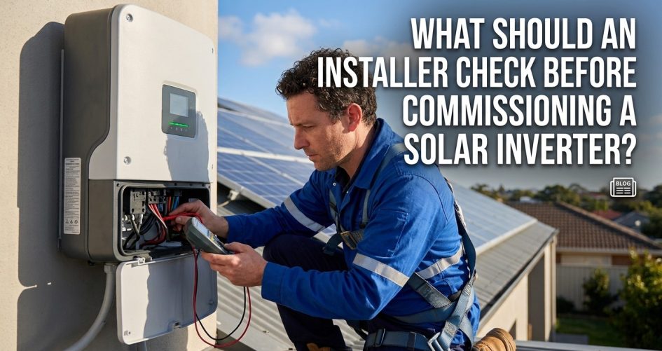
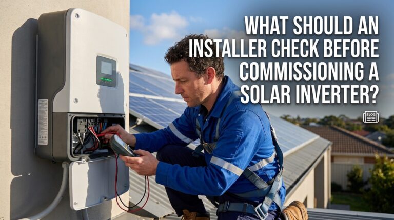
Commissioning is the last gate between a finished installation and a working solar system. A skipped check at this stage can turn into a nuisance fault, a warranty dispute, or a safety hazard later. This guide walks through what an installer should verify before energizing a solar inverter, in the order that makes practical sense. Always follow the inverter manufacturer’s manual, the local electrical code, and your utility’s interconnection requirements, since they take priority over any general guidance here.
Before touching a meter or a breaker, compare the installed system to the approved design. Many commissioning problems start as a mismatch between paper and reality.
Check that the inverter model, module count, string layout, wire sizes, breaker ratings, and disconnect locations match the plans. If anything was changed in the field, the change should be documented and confirmed as compliant before you continue.
Practical tip: Photograph the inverter nameplate, the label on each module string, and the completed wiring compartment before closing anything up. These photos are useful for customer records and future service calls.
A visual and mechanical inspection costs nothing and catches many issues early. Do it with the system fully de-energized.
Practical tip: Confirm that the DC and AC disconnects are accessible and clearly identified. A first responder or utility worker should never have to guess which switch does what.
The DC side is where solar systems differ from most electrical work: the source cannot be switched off while the sun is shining. Treat every string as live whenever the modules are exposed to light.
Measure each string’s open-circuit voltage with the DC disconnect open and the strings not yet connected to the inverter. Confirm the polarity is correct before landing any conductor, because reversed polarity can damage inverter input circuitry. Compare readings against expectations from the module datasheet and the number of modules in series, adjusted for cell temperature.
Strings with the same layout, orientation, and shading should read close to each other under similar conditions. A string that reads noticeably lower than its neighbors may point to a missing module, a bad connector, a reversed module, or a wiring error.
Many installers also perform insulation resistance testing on the DC circuits and confirm continuity of equipment grounding conductors. Follow the test voltage and limits in your local standards and the manufacturer’s instructions, and disconnect sensitive equipment as directed before testing.
Practical tip: Verify the maximum expected string voltage in cold weather stays below the inverter’s maximum DC input rating. Open-circuit voltage rises as temperature drops, so a string that looks safe on a warm afternoon may not be safe on a cold morning.
| Check | What to Verify | Why It Matters |
|---|---|---|
| Polarity | Positive and negative conductors identified correctly at every string | Reversed polarity can damage inverter inputs |
| Open-circuit voltage | Measured value is consistent with module count and conditions | Finds wiring errors and confirms the input voltage limit is respected |
| String matching | Similar strings read similarly | Highlights faulty modules, connectors, or miswiring |
| Insulation resistance | Test per local standard and manufacturer guidance | Detects damaged insulation and ground-fault risk |
| Grounding continuity | Equipment grounding conductors are continuous and properly terminated | Supports fault protection and safety |
| Connector quality | Matching connector types, fully seated, correct crimps | Poor or mismatched connectors are a common source of heat and faults |
With DC verified, move to the AC side. Here you are confirming that the inverter is connected safely to the electrical system and that the grid it will see is one it accepts.
With the AC breaker off at the inverter but the supply live, measure the grid voltage and, where relevant, the phase configuration. Compare it to the inverter’s nominal and allowed operating range. If the site has high voltage at the service point, the inverter may trip on over-voltage, which is far easier to discover now than after the customer calls.
Inverters usually need a region or grid-standard setting that matches local utility requirements. Confirm the correct profile is selected, and that any export limits, power factor settings, or anti-islanding features required by the utility are configured. Do not change protection settings unless you are authorized and the utility or code permits it.
Practical tip: Verify the busbar and breaker arrangement in the panel meets the code rules for backfed breakers and combined ratings. This is a common inspection failure point that has nothing to do with the inverter itself.
Modern inverters are configurable devices, and factory defaults are not always appropriate for the site.
Check whether newer firmware is recommended by the manufacturer for the model and serial range, and follow their update procedure. Set up the monitoring connection, whether Wi-Fi, Ethernet, or cellular, and confirm the account or portal is associated with the correct system and owner.
Practical tip: Record the settings before and after commissioning, either by screenshot or exported configuration file. If the inverter is later replaced or reset, the technician will not have to guess what was set.
| Setting | Typical Question to Answer | Risk if Wrong |
|---|---|---|
| Grid profile | Does it match the utility and local code? | Nuisance trips, noncompliance, or refused interconnection |
| Export limit | Is there a utility or customer export cap? | Violating interconnection terms |
| Battery parameters | Do limits match the battery manufacturer’s specification? | Reduced battery life or a protection shutdown |
| Time and date | Is the clock correct? | Confusing fault logs and incorrect scheduled operation |
| Monitoring link | Is data reaching the correct account? | Faults go unnoticed and the customer cannot see production |
| Backup or generator mode | Is it set for the actual wiring? | Unexpected behavior during outages |
Startup order matters, and the correct sequence depends on the inverter design. In general, follow the manufacturer’s procedure rather than improvising. A common pattern for grid-tied string inverters is to close the AC breaker first so the inverter can see the grid, then close the DC disconnect, then let the unit run its self-tests. Hybrid and battery systems usually have their own sequence involving battery breakers or switches, and getting it wrong can cause faults.
After the system has run under load for a while, inspect terminations, disconnects, and breakers for heat. A thermal camera is ideal, but even careful visual inspection and checking for discoloration or smell helps. Warm connections that are hotter than their neighbors deserve a re-torque and closer look.
Practical tip: Commission on a reasonably sunny day when possible. Low light can hide problems because currents are small and the inverter may not reach full-power behavior.
A working inverter is not the same as a commissioned system. The last stage is proving that safety features work and making sure the owner can live with the system.
Complete a commissioning record that includes test readings, settings, serial numbers, firmware version, and the date. Show the customer where the disconnects are, how to read the monitoring app, what normal operation looks like, and who to call if something goes wrong. Leave copies of manuals and warranty registration details.
Practical tip: Follow up after the first few days or weeks. Reviewing production data and any logged events often reveals shading, settings, or communication issues that were not visible on commissioning day.
Not without checking first. Verify polarity, voltages, torque, grounding, and configuration before startup. Also confirm any required inspection or utility permission to operate has been granted, since operating a grid-tied system without approval can breach interconnection rules.
Open-circuit voltage is the highest voltage a string produces, and it increases in cold conditions. If a string exceeds the inverter’s maximum DC input voltage, the inverter can be damaged. Checking the measured value and calculating the cold-weather maximum protects the equipment.
Do not repeatedly force restarts. Note the exact fault code, look it up in the manufacturer’s documentation, and check the likely causes, such as grid voltage out of range, incorrect polarity, insulation faults, or a wrong grid profile. If the fix involves internal components or protection settings, contact the manufacturer or an authorized service provider.
Yes. In addition to the checks above, you need to verify battery wiring, communication between battery and inverter, correct battery profile settings, and any backup-load wiring. Follow both the inverter and battery manufacturers’ procedures, because the startup order and settings can be specific.
A written checklist makes the process repeatable and gives you a record if questions come up later. It also helps new team members learn the routine. Adapt it to each project rather than treating it as a formality.
Good commissioning is methodical: confirm the design, inspect the work, verify DC and AC wiring, configure the inverter correctly, start up carefully, and test the safety functions. Document everything. If you are sourcing inverters, mounting hardware, or accessories for an upcoming job, Emston Tech at emstontech.com can help you find equipment that suits your project. Always confirm compatibility with the manufacturer’s specifications and local requirements before installation.
just now